Links
Tags
Building a Synchronised Christmas Lights to Music Display - Part 3
In less than a month, I'm expecting to find myself scuttling across the roof putting up a lot of LED strips and somehow mounting the props mentioned in my last post to the house, and on the front lawn. Unfortunately for me and a package of 1,000 lights and additional connectors is still in the mail has now been delayed for several weeks due to COVID-19. Thankfully this package is to build out the LED matrix, so perhaps in a couple of weeks time I'll be detailing how that gets built as a shorter post. In any case, there's still been progress.
Snowflakes out of scrap
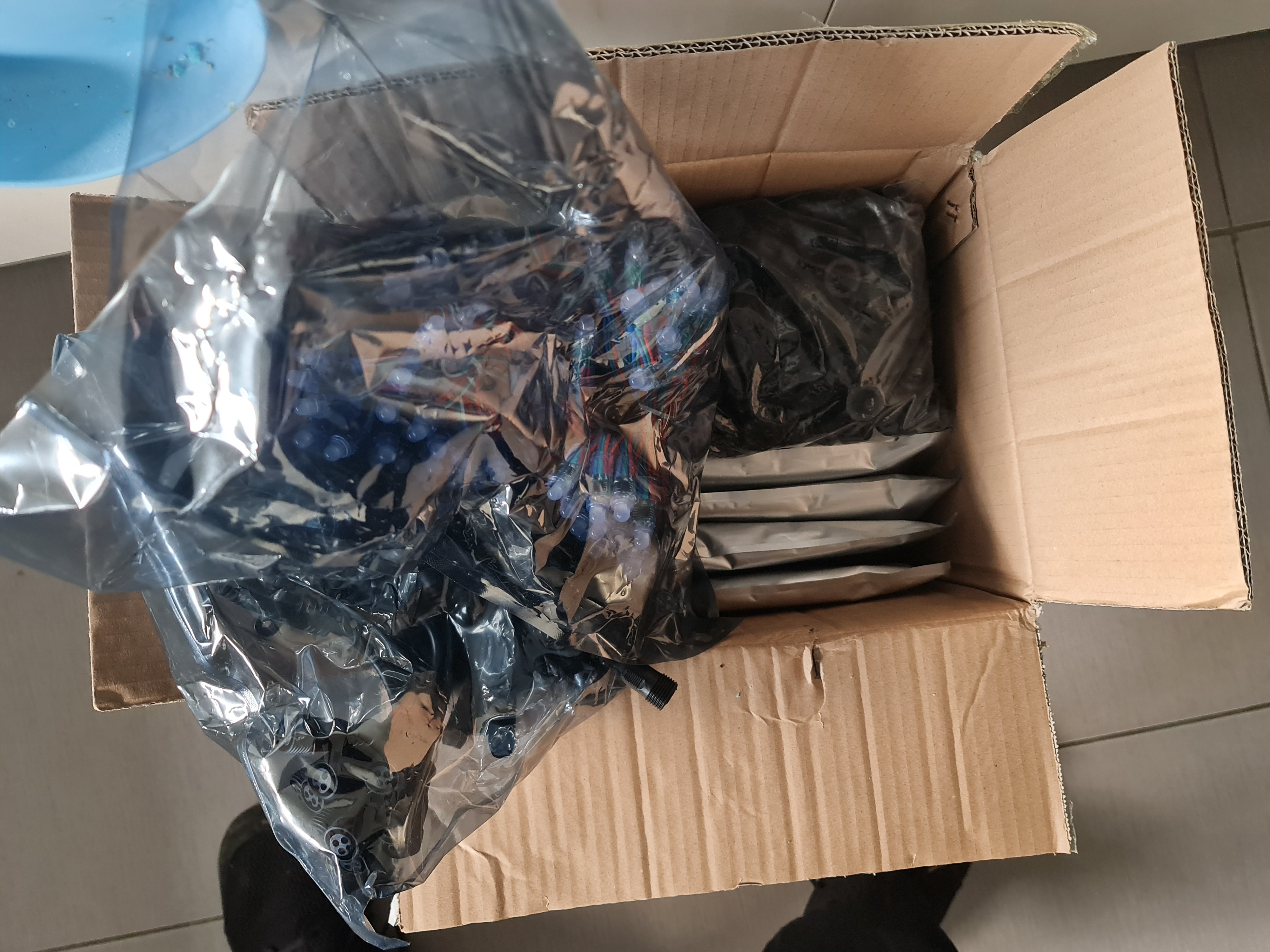
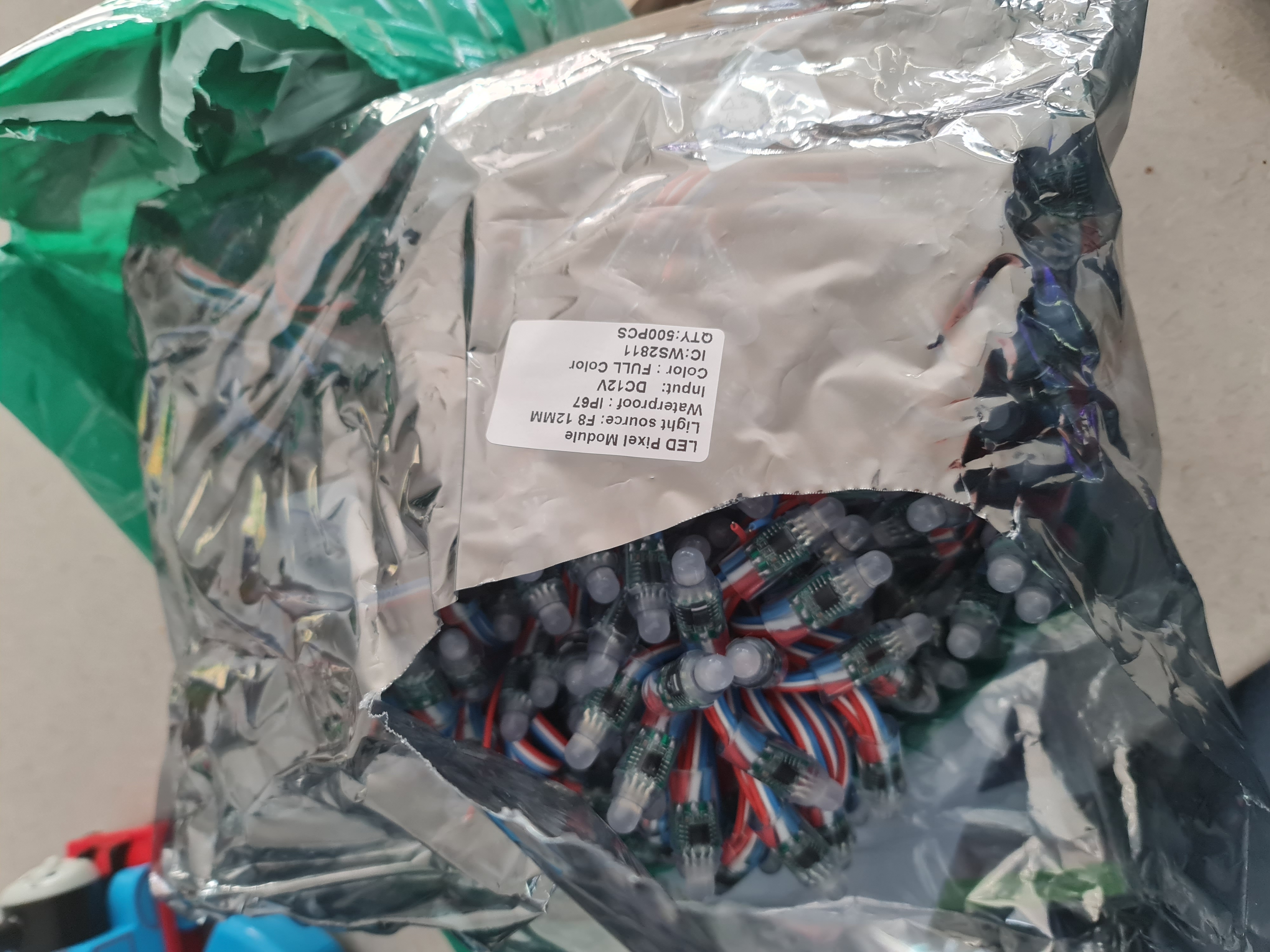
I received my order from China a few weeks back with all of the LED strips, cheap 'promotion' 5V pixels and a number of cables needed to wire this show up. These 'promotion' 5V pixels did come with a number of warnings in the forum around voltage drop and drop it certainly did (these were connected using 24AWG wire so the 'workaround' was to power it from both ends. Suffice to say, I can't see them being particularly useful unless you love to solder. Ultimately I did find a use for them, and the result was quite effective - so much so it's up there with one of my favourite props from the whole exercise.
So... out comes Sketchup with a star and fork using something geometrically symmetrical to fit between the pillars of the garage. The end result is pretty neat.
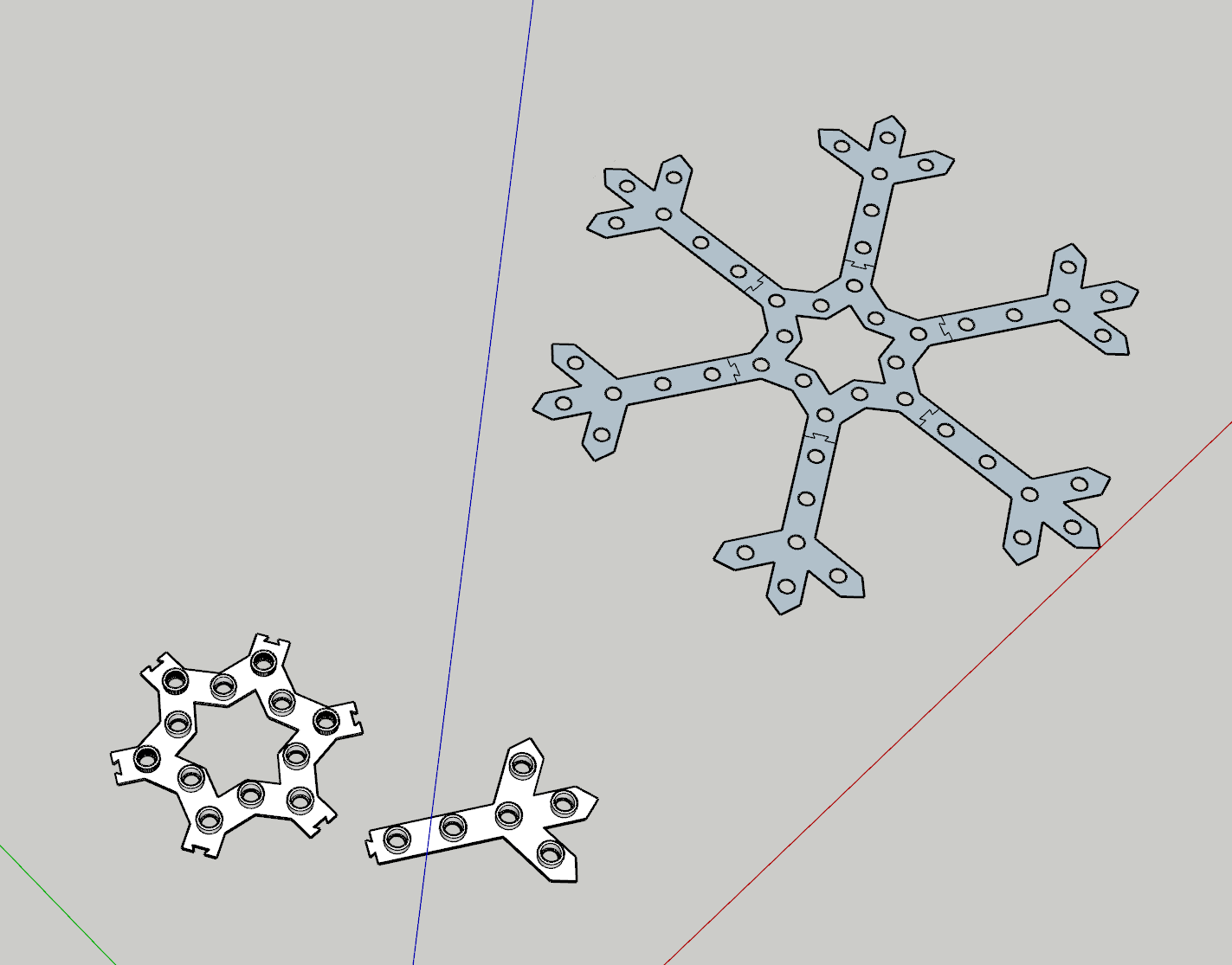
Now the original design here attempted to use angled and thinner connectors, but they proved after printing to be fragile and not easy to 'bash in'. I also played around with thinner bodies and longer 'tubes' to place the bulbs in. There was some merit to the tube but 3mm was just too thin for the rest. So I settled somewhere around 5mm for the width using the Gyroid infill type at 25%, with the bulb holes out to 10mm. Also not quite visible here was I put a 1mm "lip" such that the bulbs can be pushed in place easier than trying to jam them in the 12mm holes. That is, the 1mm piece was 12mm in diameter with the rest of the hole at 13mm.
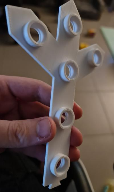
So... back to the printer at 5mm width, 10mm holes, 1mm lips and what not. The only suggestion may be that I might have made them slightly larger if I were to print them again.
Now this is my favourite part. To get good adherence, I use a product called 3DLac - it's basically a hairspray type product that I spray onto a 200mm x 200mm glass panel. This keeps the ABS well adhered to the panel, with the side effect of a shiny glossy side. I've not used it for other props, but given how the lip was printed and the holes behind the scenes, I've had to use the shiny side as the exposed side. And I must say - this has really made these 'scrap' snowflakes pop!
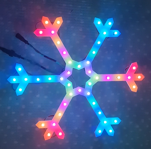
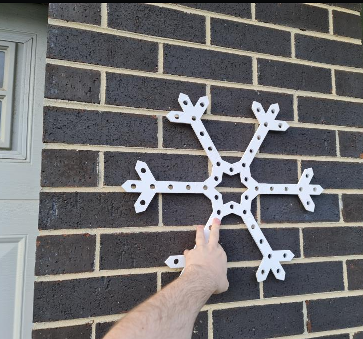
So having done this, I've printed a second one and added it to the show. I mentioned earlier about the 'Voltage' drop on the promotional pixels - well, luckily enough normal 5V pixels in strings of 50 appear to light up just fine without any injection. At 24AWG though, the wire is just not thick enough to carry that 5V all the way down the string. By the time you get to about the 35th pixel, at even 30 or 40% brightness, those whites start turning other colours and start blinking. To solve this, I've got a crazy connector at the origin. Basically you inject power at both ends of the 50 pixels and the problem goes away. You can see how impractical this may be if the prop was much larger than 50 pixels. Also - the work to do it, to save a few dollars in my opinion is just not worth it. These pixels from China were priced very well - $9 a string. But the same seller also sells proper gauged ones at the normal size for around $16 AUD complete with the right connectors soldered on. For the extra $7, you get the two connectors pre-soldered, don't have to use heat shrink and don't have to worry too much about splicing wires in a crazy way. Depending on how many of these kinds of snowflakes or smaller props you want, you may save a few dollars by making lots in bulk ... but definitely factor it in when you've got the rest of the house to do.
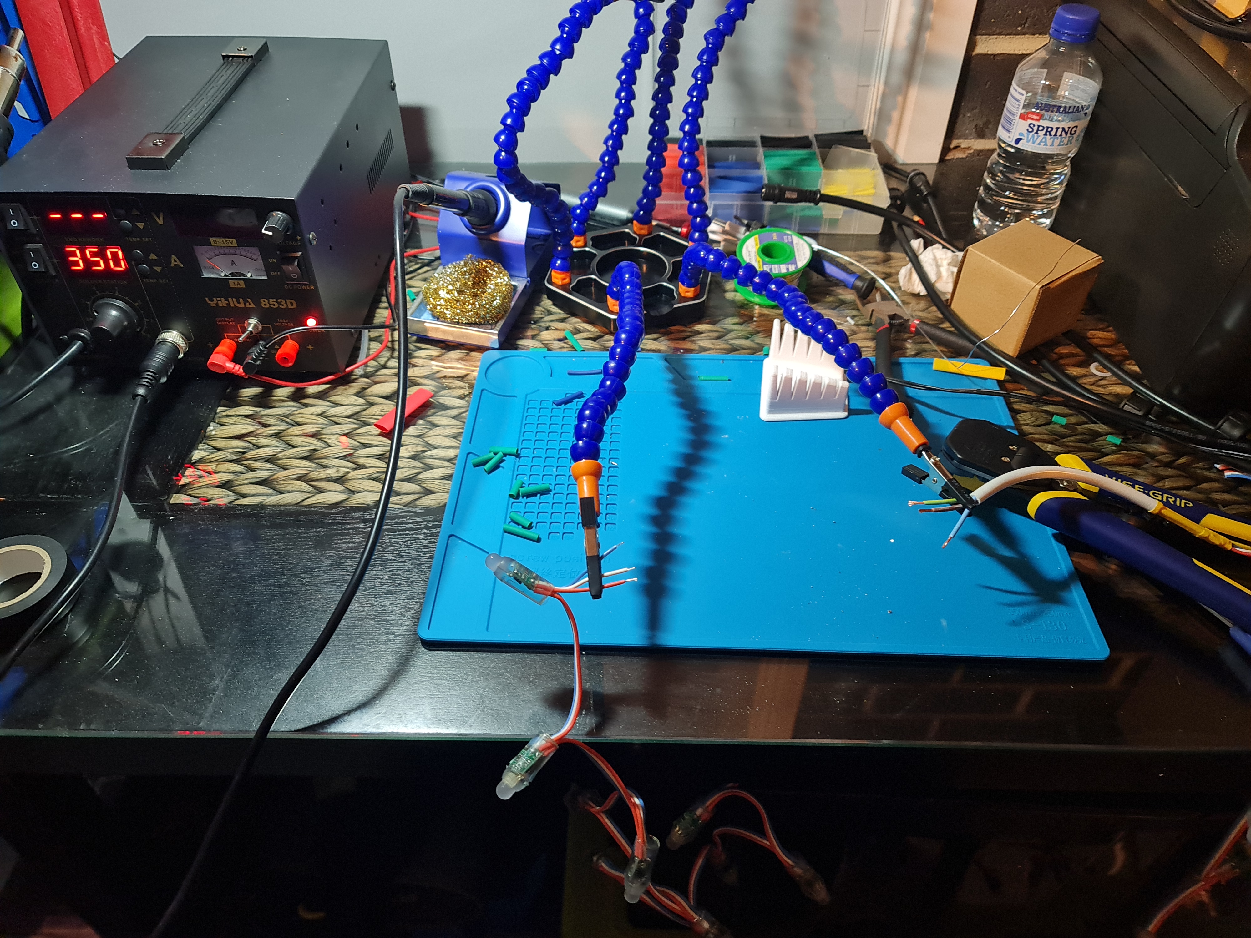
Preparing for the Matrix by soldering more issues
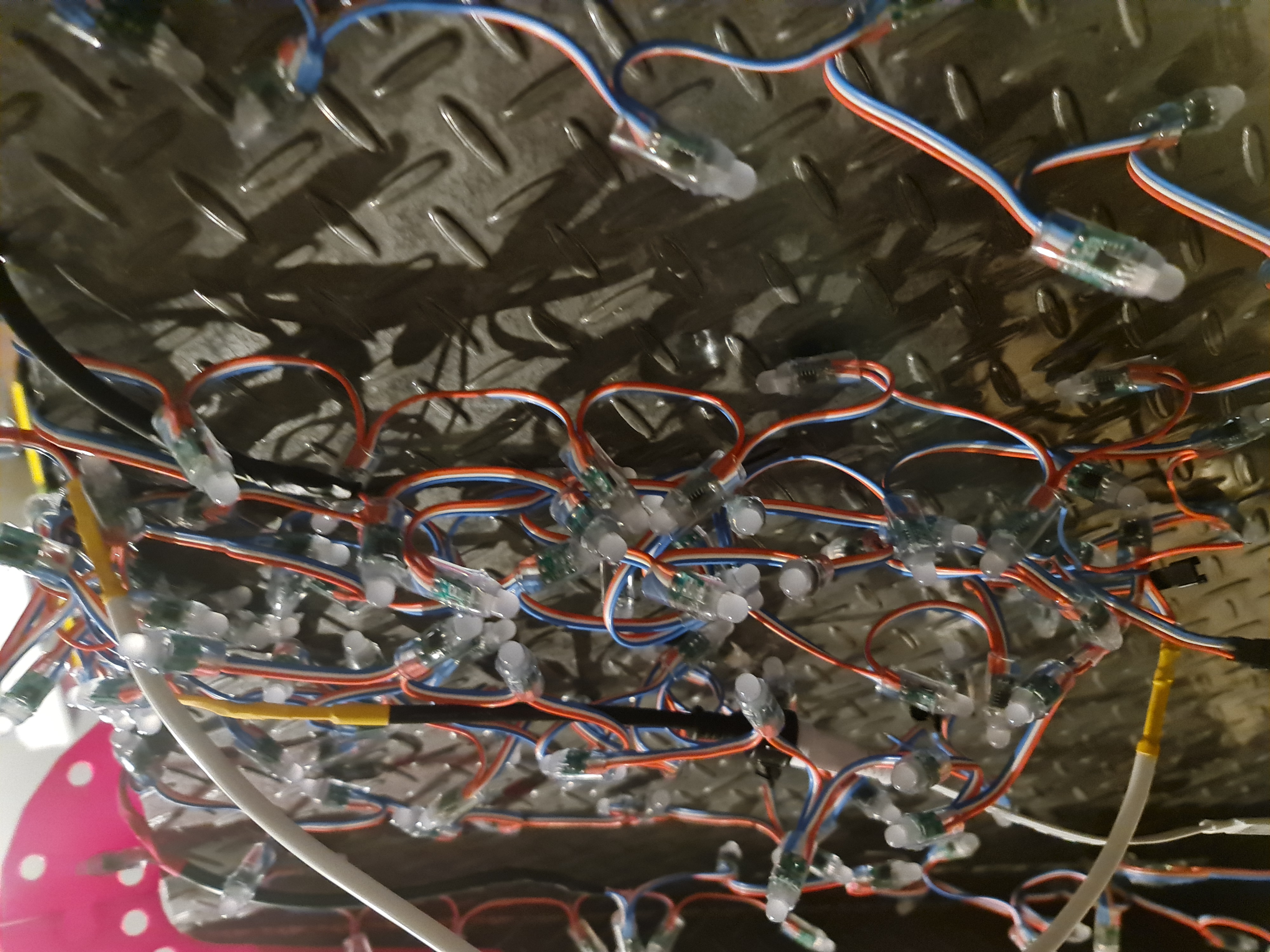
So to get an idea on what pixel spacing I need, I've needed to solder up all of the remaining bulbs to get enough pixels for testing. So I heat up the soldering iron, cut up a whole heap of heat-shrink and start assembling the bulbs.
A few hours later, and I've got lots more bulbs to use.
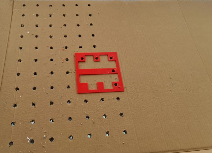
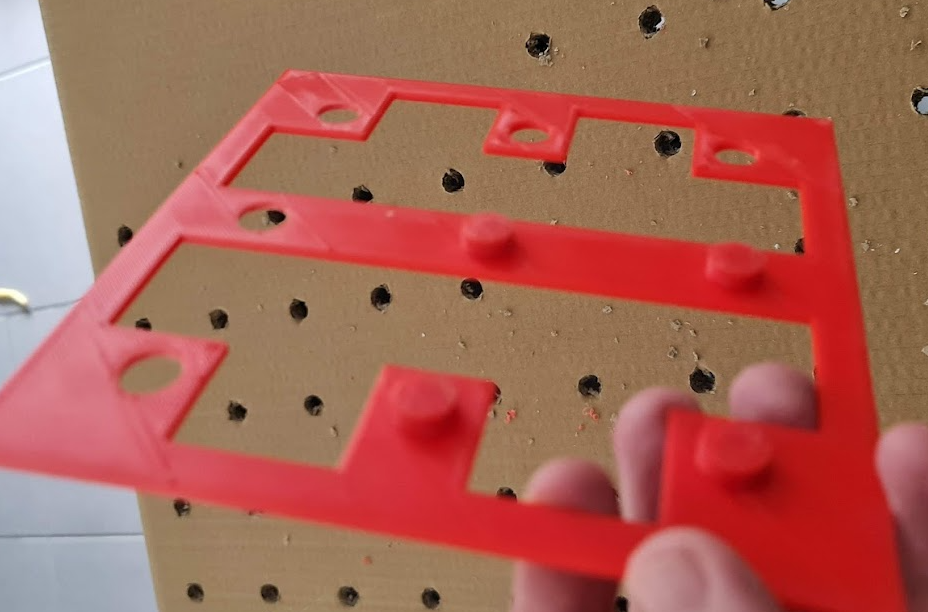
So I figure a 5cm spacing between the pixels will give me something of a 50 x 20 panel. It's not going to be high res by any means but should be enough for some blocky Santas, Reindeers and Text on the panel. To assist, I've designed and printed two templates. One with 9 holes to draw the starting bits on the cardboard and another with 5 holes and 4 plugs that can sit in the hole so I can drill through to get some semblance of symmetry. With some pretty big purchases recently, I've got plenty of cardboard to sketch out a miniature version of it - so time to get drilling.
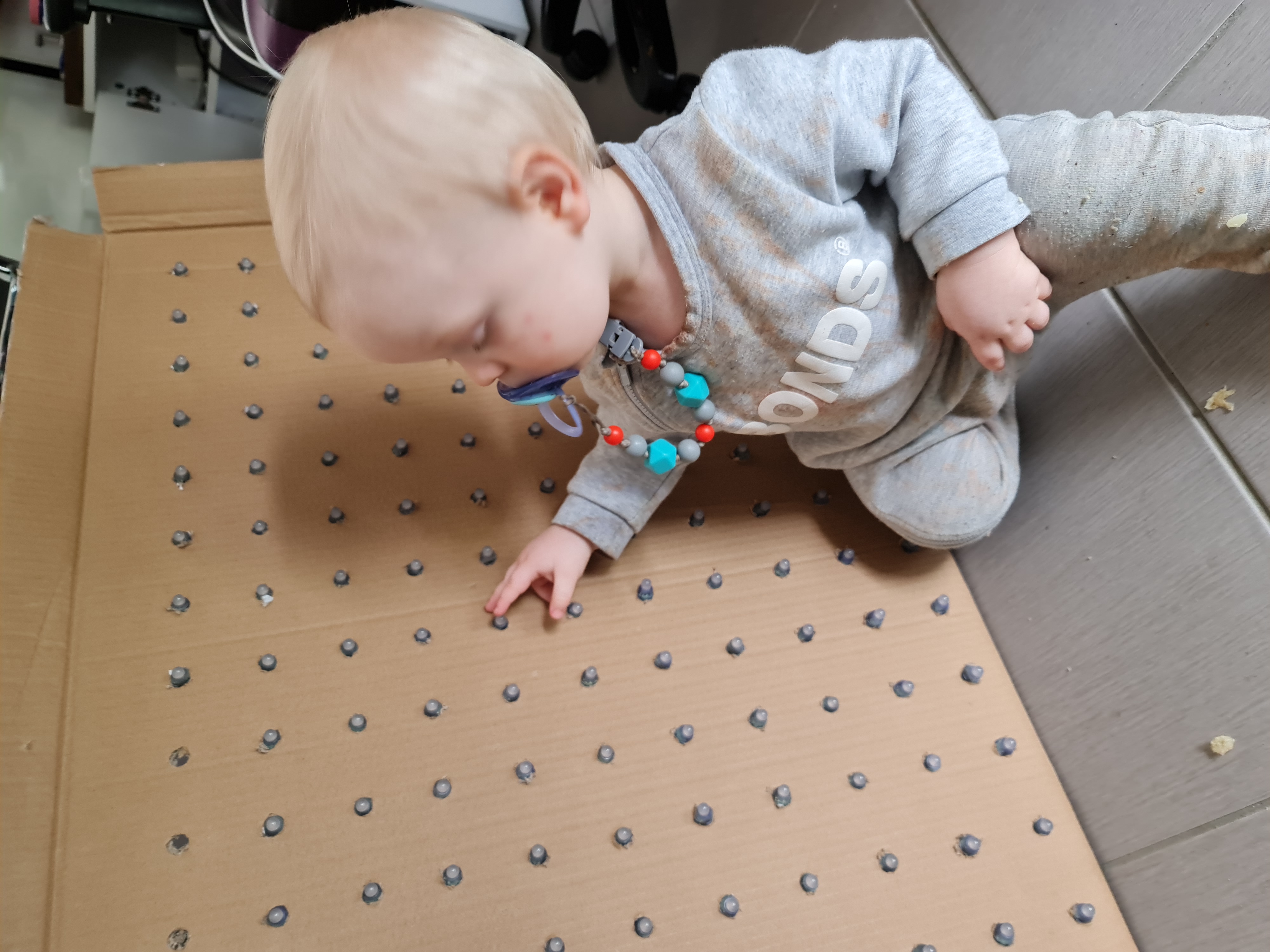
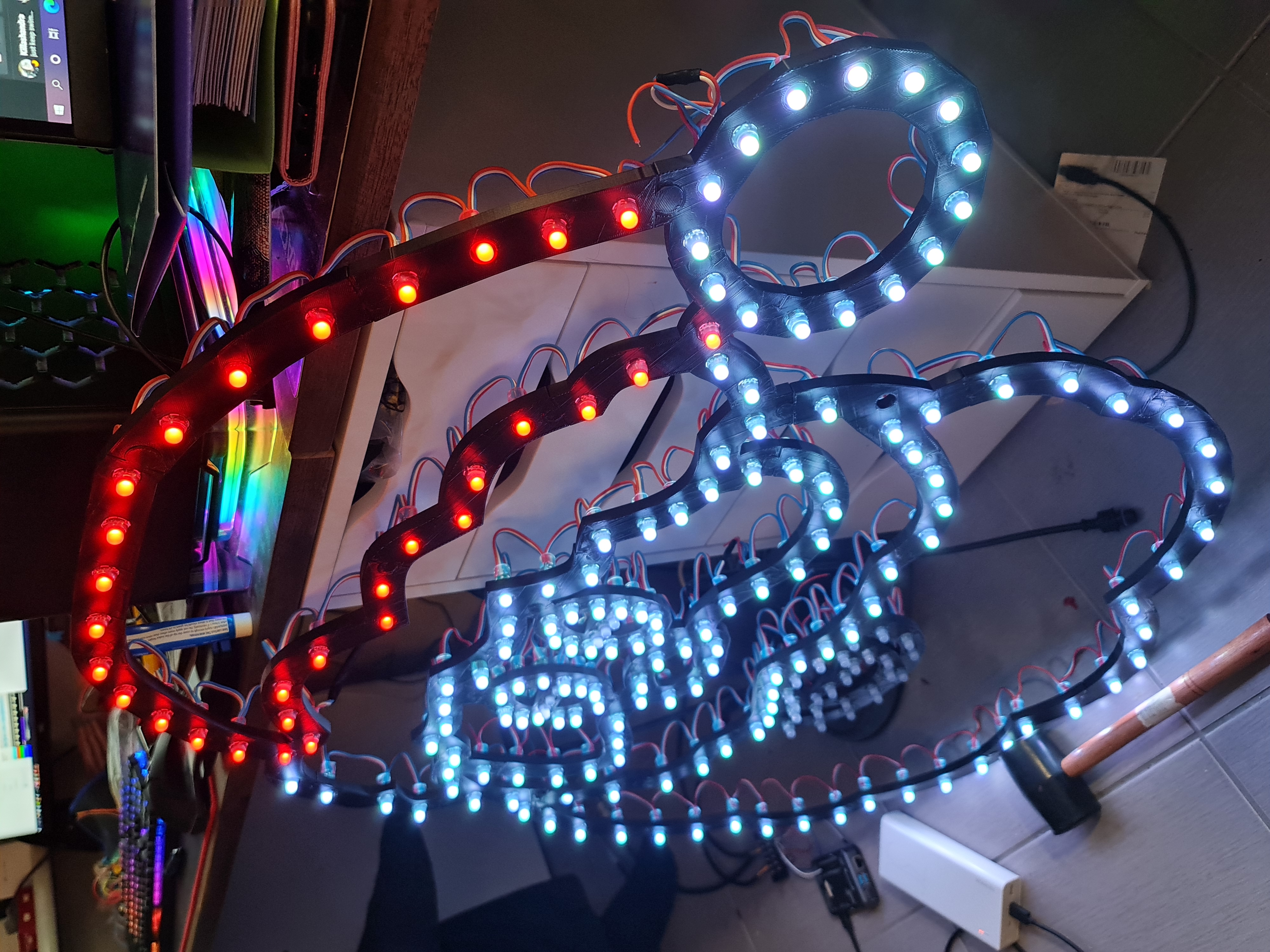
With all the holes drilled out, and the pixels all populated, my son gave it a good test.
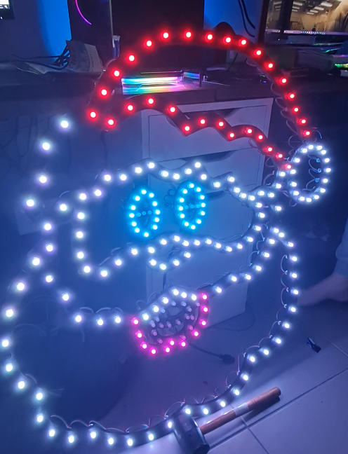
Now it's time to put some pixel art up and the first thing I notice is the colours were slightly off. Now I'm not a great artist by any means, but that red stick figure up there looks familiar... although I don't think I'd want to meet him in a dark alley.
I had originally planned to only go 16 layers (800 pixels total) but these pictures pointed out that I probably need a couple of extra each side to allow for any borders or two lines of text (8 pixels high each with some spacing).
I'm pretty sure at night these will look alright but there are a few things to note that might seem obvious to those that have worked with lights before:
- Brown is an incredibly difficult colour to reproduce. Browns, yellows and oranges in daylight are near indistinguishable - at least on these pixels.
- Spacing even at 5cm does need some considerable distance to be readable. I'm hoping that those viewing the show will be a good 6m away at least.
- Density is good - but you will quadruple the number of pixels (i.e. 2.5cm spacing would build a 100 x 40 display - some 4,000 pixels! that's getting quite expensive and still not particularly high res).
There are a few alternatives, like P10 panels - they're a 32 x 16 panel at 10mm spacing. That gives you 320mm x 160mm. To make a similar size matrix, I'd need 8 across and 6 down (maybe 7, depends what your margin of error is going to be). Apart from the insane cost of buying 48 of these things, let alone the power supplies required to power all those pixels, you'd get a decent resolution - 256 x 96 - but ... I don't know. I've never found those sorts of matrixes to be any good for things other than clearer text. I think it takes something out of the 'twinkle' effect. And I'm sure people say that about LED Strips and WS2811 Bullet Pixels too.
Then there's the possibility of using a Projector. I could project images, but I think the two techniques would create a bizarre distortion as the viewer where there's bright lights somewhere and a too-high resolution with a different brightness just not quite creating a synergy I like to see in displays. So suffice to say - I'm hoping the matrix works but I wouldn't be totally upset if I ended up replacing it with icicles or maybe a mini-mega tree in the future. A few P10 panels for some text might not go astray - but it might only be a 6 x 2 kind of deal rather than all 48 of them. Plus I think there's something to be said about Tom BetGeorge's show and his use of a matrix on his Garage Door that I might like to replicate at some point in the future...
Accessories to power the show with
There's been a lot of posting about the props and the fun stuff. Behind the scenes stuff is also important. This is where things get a little more interesting but also more familiar. Before I start, if you're reading this planning on running your own show, there are plenty of 'out of the box' kits and what not that you can buy for the show execution perspective. Certainly more out of the box than my setup here.
One of the more common boards people are buying to run their shows with include the Falcon Boards from PixelController.com. Now when I say "out of the box" I don't mean you're going to buy one of these and all the lights and power supplies to go with it in some kind of kit, just that in order to control your lights - these are fairly plug and play when I look at the instructions for these. As you may appreciate, each one of these does cost a significant amount of dollaridoos - and at these prices, I would have been turned me away from building the show in the first place. Don't get me wrong, I can see the value in those sorts of boards and the convenience you can get by using Cat6 everywhere - especially if you don't own gear already. But these, paired with 'differential boards' and receivers, can cost a fair chunk of coin so you're going to want to be absolutely sure of heading into this 'hobby' by preparing to land quite a few hundred dollars on controllers.
Now regular readers will know I have draws full of Raspberry Pi's and Arduino's. You can buy the Raspberry Pi Zero with Headers for around $20 AUD in Australia (albeit there are shortages at the moment), and even less if you're prepared to solder them on yourself - and I'd suggest that if you are planning to start a show of this scale, you're going to become very acquainted with a soldering iron to be able to perform such a thing. If using Pi Zero's, you're going to also want to think about Ethernet via USB. I'm unsure on how things will cope running 2.4Ghz Wifi, so consider that in your plans. In my case, I had several Raspberry Pi 4's from a Kubernetes cluster that will be running the show for me this year. When I purchased mine, they were around $60 AUD each from PBTech in Sydney (some New Zealand company that seemed to be able to ship from Australia). That's not their usual price - they can be $100 AUD or more. They don't have to be Pi 4's, this is not CPU or Memory intensive - as evidenced by the ability to use Pi Zero's so if you've got Pi 2's and Pi 3's lying around, use those. For my particular show, there'll be 4 x Raspberry Pi's in total.
- 1 x Raspberry Pi to control all Props (singing trees and Santa, as well as the lawn props - some 1,150 LEDs).
- 1 x Raspberry Pi to control all LED Strips (roof mounted and front of house mounted - some 1,600 LEDs).
- 1 x Raspberry Pi to control the Matrix and 5V Props (matrix is 1,000 LEDs, the other props may be 100-200).
- 1 x Raspberry Pi to act as the master for all these other Pis.
So if you were to buy all this stuff up front, we're either at $80 AUD because you went the Pi Zero model, or $250 AUD+ for new Pi 4's. Now that Falcon board doesn't seem half bad, even when you start factoring in differential controllers. On the other hand, if like me you have a draw full of them - the net cost is $0. So for me, it was a win to stick with the Pi's.
There are only two GPIO pins that really support the data port for WS2811. They apparently power around 800 LEDs per pin, but that's quite a subjective topic based on how many frames per second you can push. I've tried a few things and won't have an answer yet on frame rates until it's installed and running - but I'm not too worried here. Most people watching will be mesmorised by the lights rather than worrying about framerates.
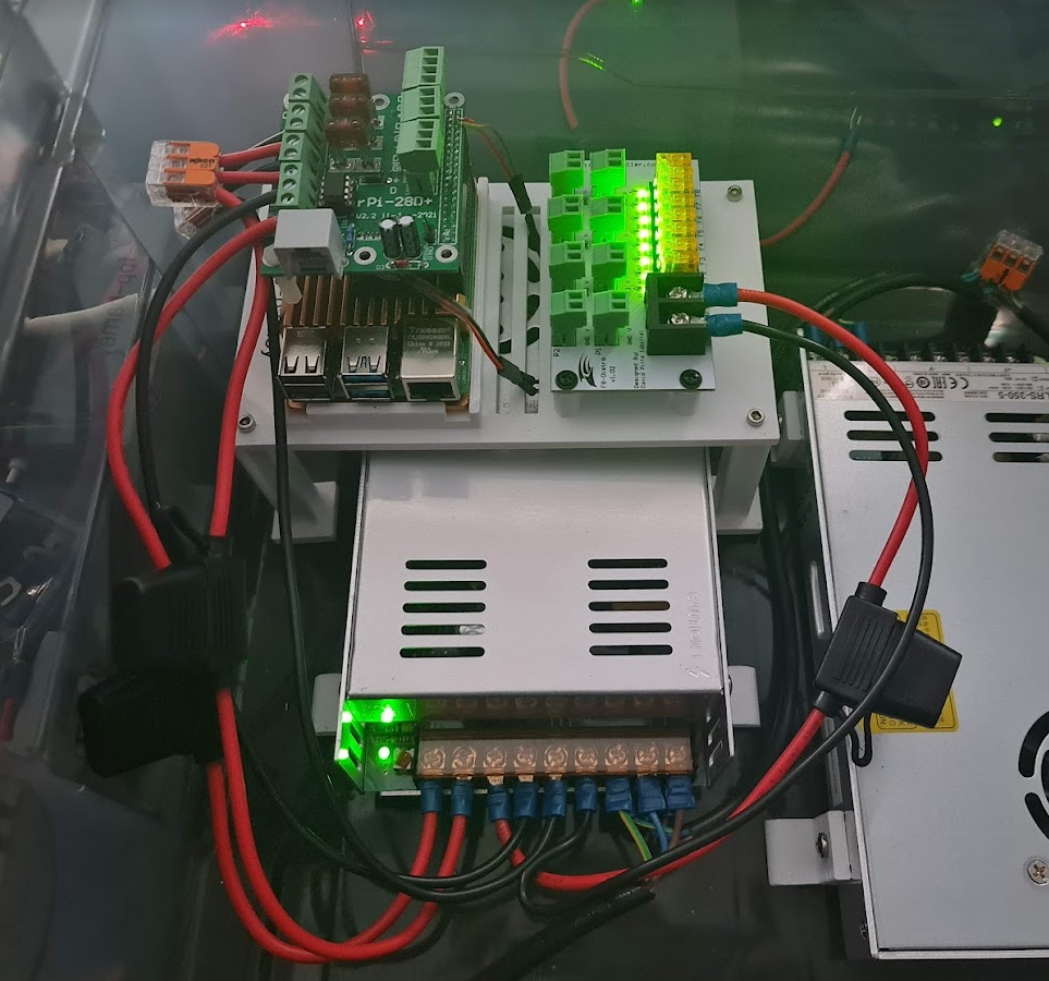
Hanson Electronics - a local supplier has made a custom board to help deliver the power to 'two strands' of WS2811 as well as other things. It comes totally fused and will power the Raspberry Pi itself with a 12V connector or a 5V connector. This 'all in one' board makes this a heck of a lot more convenient to wire things up safely (albeit I did fuse the inputs for both the Pi power and the LED outputs, just in case those cheap power supplies play any tricks on me). The board is the RPi-28D+ - and comes with fuses already installed. Absolutely beautiful. They're well priced too at $38 AUD each. I need 3 of them, so a little pricey in that regard - but they're going to save a lot of time and heart ache trying to power these things via other methods. So I think they're worth it.
- 3 x RPi-28D+ Hats to run WS2811 strings. Around 1,600 pixels supported per hat, 800 per port. You can push more but apparently things might not push the full frame rate. That's OK - adjustments can be made once it's all set up and going.
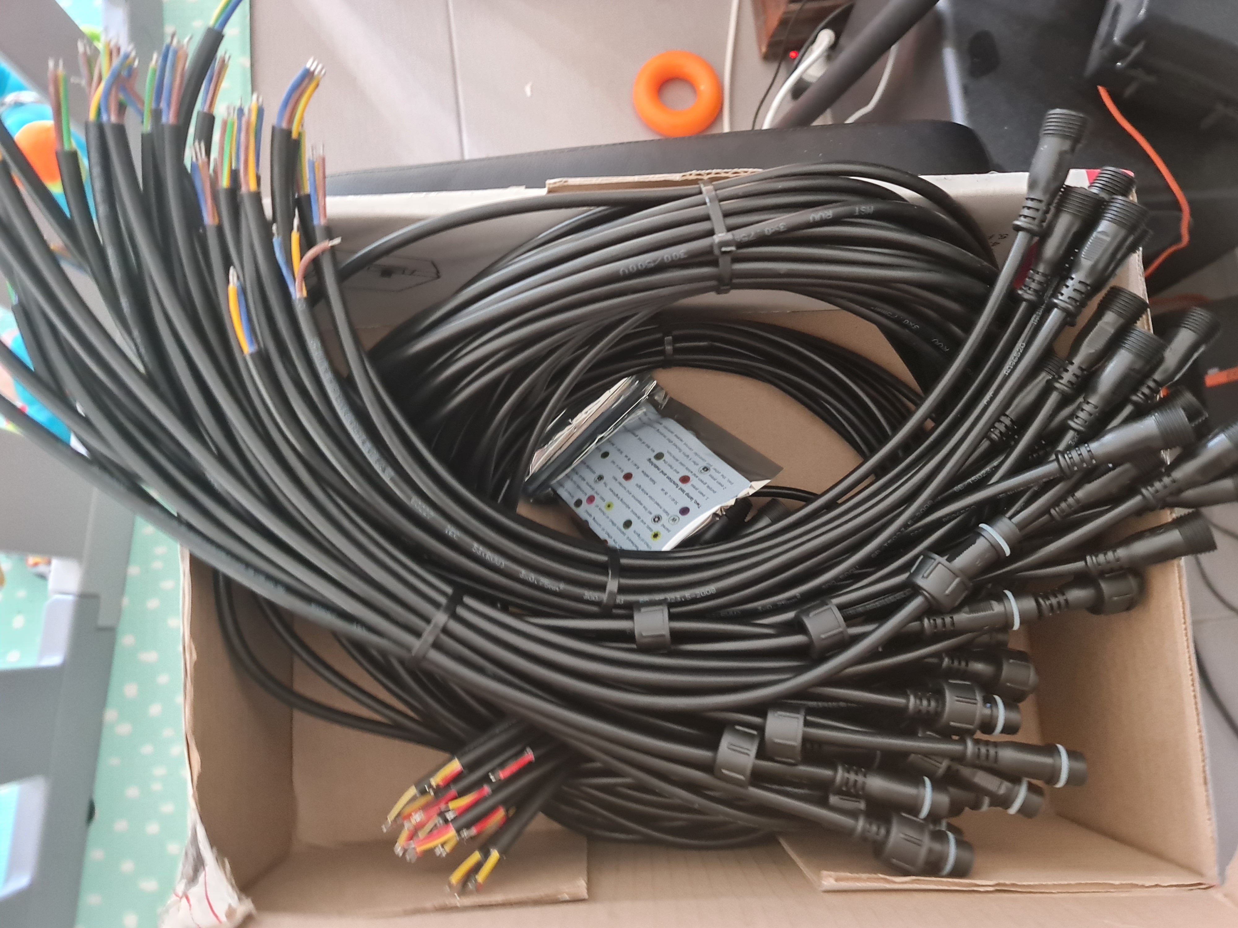
In order to distribute power to each of these pixels (Voltage Drop and having enough Amps without burning wires out), I needed to think about fusing them. Amazon had a good deal on these 12 V Rextin Power Supplies - the same company that did the LEDs, so I thought I'd give it a go and buy two of them for the 12V pixel stuff. So with 25 A input from these, I needed to figure out a way to get power to the LEDs.
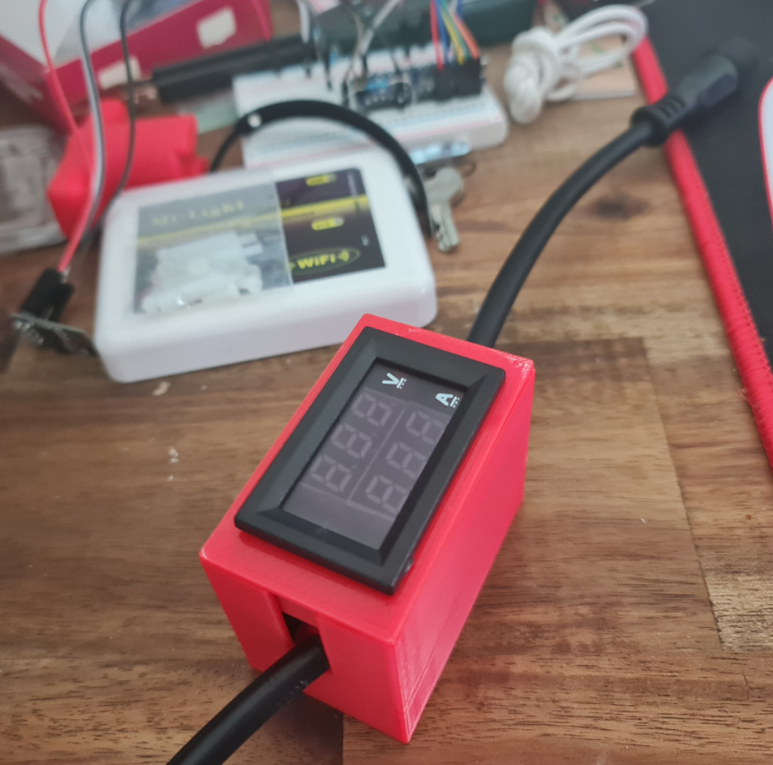
Now a word of warning, this is all anecdotal. There are plenty of videos on YouTube explaining this better than I can so do your research before taking on power injection. Basically I found that if I have some 200 12V pixels in, give or take, I can power Santa Claus on full bright white start at 12 V at the input side and have a drop to about 8 V at the other end of the wire. If I were to add more pixels without injecting power, eventually the Voltage Drop would be so low that there would be no power left to light up those bulbs or you'd get some really strange colours. So to handle this, you need to make a sort of T Junction between those props (or strings if it's one continuous one). At that T junction, you inject a further 12V into the line such that nearby pixels have access to 12V and not the dropped 8V - this is done from the same power supply. Typically I find only 3-4 Amps might be consumed, using the tester I've made using that (picture below).
So in order to distribute power, I'd need several 12V lines running from the power supply to power things. The trick is, the power supply only has 3 outputs that are unfused - so this brings about another situation you want to solve - and that is what happens if you get a short. You certainly don't want some 30A passing down your tiny little wires, unless you plan on having a very toasty fire going on.
Thankfully, this problem has been solved several times over. In my case, from that PixelControllers group I was able to locally source from Light it Up LEDs the F8-Distro controller for around $20. I procured 4 of these, complete with fuses ready to add to each Power Supply. With a bunch of T Connectors in the China order and some more coming from Light it Up LEDs, I should have plenty of options in order to inject power where necessary.
- 4 x F8 Distro Controllers to distribute power
- 2 x 12 V Power Supplies 300W
- 2 x 5 V Power Supplies 300W
It's possible to use Server Grade power supplies, and now I'm kind of kicking myself for chucking out old IBM servers that had 700W power supplies in them - they would have made for great cheaper power supplies if I could extract the 12V from them - but anyway a thought for anyone that may have old ATX and Server Power Supplies around. There are a lot of breakout boards, especially targeted at things like Bitcoin rigs, that can turn those power supplies into readily available 12V DC sources.
So with the parts above out of the way, it's not cheap but spending just over $250 AUD on controllers and power supplies meant I'd saved an absolute bucket load on controller stuff for this show. I'd have liked it to come in just a bit cheaper but this is certainly the area you want to be sure on as there is a genuine fire risk here if you get it wrong.
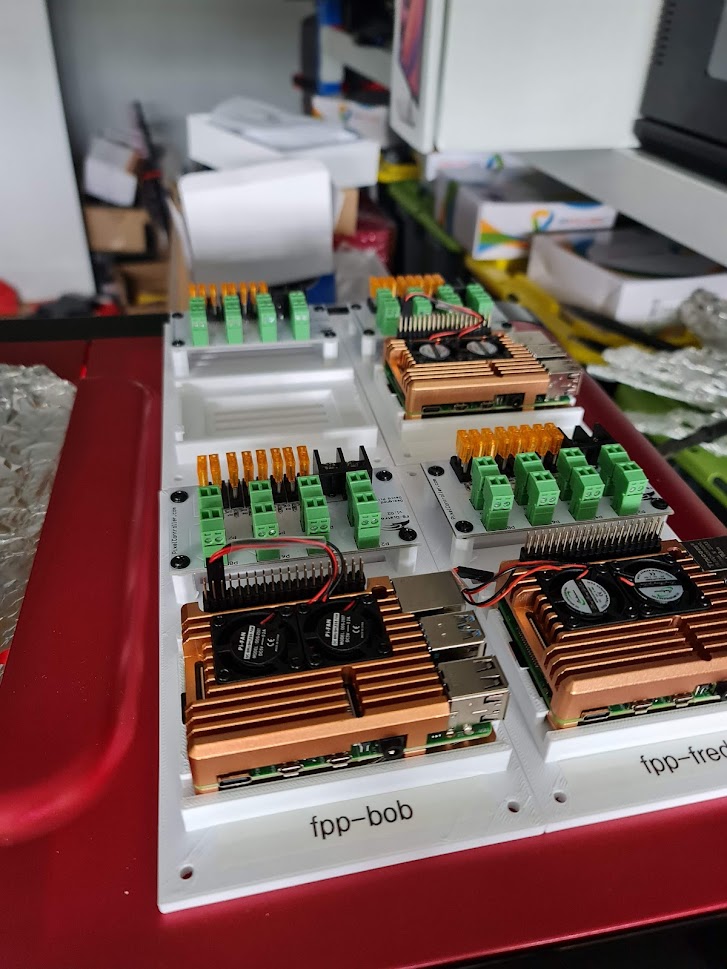
Now off to the 3D printer again to design some mounts for the Power Supply and Raspberry Pis. This mount took a few goes to get right again. This design uses a clip system to keep those Raspberry Pi's mounted in a way that allows those 'Armour' fans to sit in. They're very snug in there, they won't be escaping out. The F8 Distro boards sitting next to them are screwed in using some Brass Threaded Heat Set inserts. Basically you use the tip of your soldering iron to melt those into place so that you can screw things into them. Note that one of these is missing a Raspberry Pi. This one will live with a 5V power supply that's only supplying additional power to some LED strips.
With these boards and distribution blocks sorted out, it's time to mount the RPi-28D+ hats and start delivering power to these things.
Having raided my draw for 12 AWG wire, fuses and Wago nuts for distributing the 12V line between the two strings of LEDs, I'm pretty happy with the outcome here. All that's left is to wire up the other two power supplies in the same waterproof tub before putting the box through a few tests.
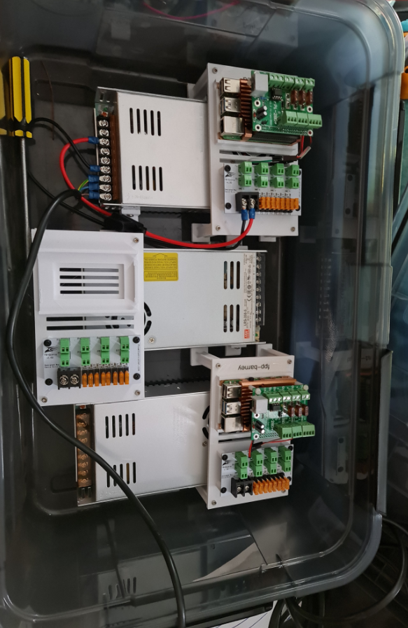
There are still a few more steps here. One is to put a Smoke Alarm or heat detector in here. The last thing we need is a fire to go on within these boxes. There are fans yet to be installed (need to get a gasket system going to keep this box sealed), and I need to test that the box is genuinely waterproof before drilling lots of holes in it. None-the-less, it's a tight but 'good enough' box I think to get started with. There's a fourth box still to build - this will form part of the roof kit. That one will absolutely need a heat sensor that can cut power to itself - and a warning via some other passive system (i.e. smoke alarm) that if things start getting too hot up there it can be manually disconnected. I'm a little paranoid about it and I don't think it's too much to have those protections in place.
Anyway - hope you've enjoyed this post - this last section has been a bit dry. Once it's all assembled, I might even look at doing a video for how it's all assembled. Hopefully the next post can reveal the LED matrix and some of the supporting brackets to go with it. Come on AusPost, deliver already!
Building a Synchronised Christmas Lights to Music Display - Part 2
Woah! Never expected that Christmas Lights would take up as much time as it has so far. I wasn't under any illusion that it wouldn't take time - but as I write this on 2nd October I'm reminded that I'm just over a month away from hanging stuff up on the house and running my first synchronised light show.
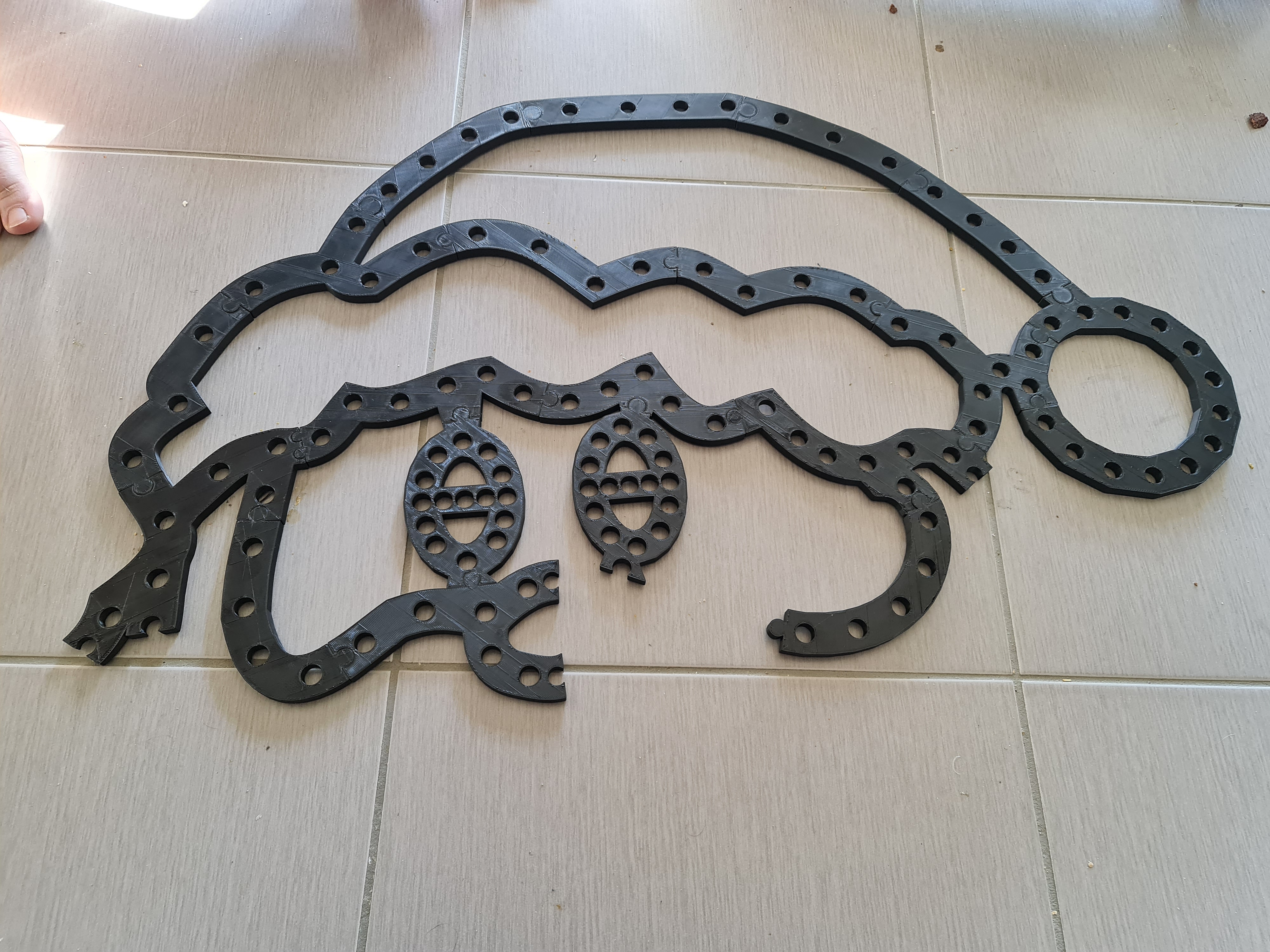
First - the props. In my last post, I left you with a picture of my 3D printed singing Christmas Tree and a view to make some new props. I started working on a similar layout to the singing Santa from Boscoyo albeit at a suitable size for the space it'll be mounted in. The process was similar to the Christmas tree - eyeball the layout from xLights, reduce the size to the space I wanted to occupy (around 60-70cm square) and draw in new 12mm holes for the bulbs to sit in.
The Singing Santa
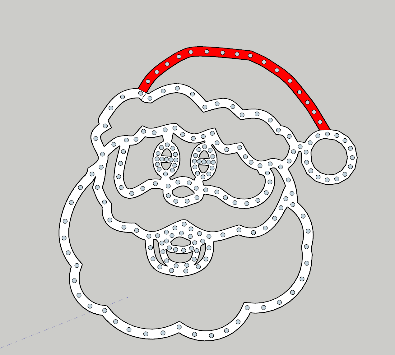
I must admit, he looked a little creepy in this one. Some things I learned from the previous print is to try and keep bulbs at notable points. While you won't see the plastic once printed and lights are up, not having the lights right in the corners and edges means the light up will look slightly off. Also - Santa needed a red hat and white outlines for this setup so while I didn't end up printing out the plastic in white or red, these would roughly serve which lights will light up those colours.
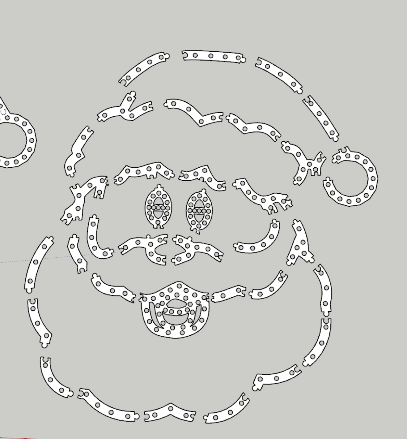
This one was a little more challenging, especially with the mouse piece just breaching 200mm (although using some angling, eventually got this to print. The downside of this was the lack of supports around the beard. There's a lot of weight in the top half reasonably well secured. I also noted that for at least one set of lights, I'll need to solder on a joining wire between parts to ensure we've got enough distance to wire him up.
These props will be mounted to a PVC pipe frame so I'm not ultra worried about it - but if I were to design this one again, there'd be two supporting brackets either side of the beard, up to the side of the mouth, and a couple of smaller chunks between the mouth and nose.
You'll note that the success of the 'train track' join style, I've used that again here as it's been a good way to join plastic together with a solid fit without removing much plastic.
in the lead up to Santa finishing printing, my delivery from Amazon arrived - my 1,000 lights that I'd need to cut, splice and add pigtails to that I'd ordered from Light it Up LEDs. Now I must admit I wish I discovered Light it Up LEDs much earlier than the Amazon order - the bulbs were a little cheaper, and he had LEDs with the connectors already soldered on. This would have been a tremendous time save, but none-the-less I had these bulbs and I had to cut off odd numbers of bulbs. For this guy, he is 203 bulbs so ... 4 x 50 + 3 from another strand. Another learning here to try and get multiples of 50. For reference, the Christmas Trees are 156 bulbs. If I could reduce (or increase) the density, it would have made wiring easier.
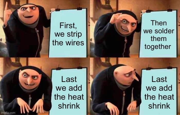
I don't have a lot of pictures of me soldering wires away, but it's fair to say I've soldered a good couple of hundred pieces of wire together. I've got pretty good at it too. But there's one thing I kept missing... the bloody heat shrink. I really need to print this out and frame it, frankly.
Anyway... with pigtails attached, wires spliced with extension wires and some waterproofing done (silicon around the exposed connectors), it was time to turn Santa on. And wow - it looks great.
Now the eagle eyed of you may note there's a hole with a bulb missing! Yep - I missed one bulb. And yet... I didn't have any leftover bulbs. I'm not even sure how both errors lined up. In any case, always remember to count your bulbs. Sorry Santa, but you'll probably be replaced next year.
The Candy Cane
Ok class, time for a bit of Math. If I have 1,150 bulbs, Santa consumes 203 and each singing tree takes 156 bulbs, how many do I have left? Well, of course the answer is 635 left that I need to distribute between 5 mini trees + stars and 4 candy canes. Each mini tree would be around 90 bulbs (70 for spokes, 20 for the star) so that leaves around 185 bulbs left to use. That leaves around 40 bulbs per Candy Cane left, with some spares for repairs I might need to do along the way.
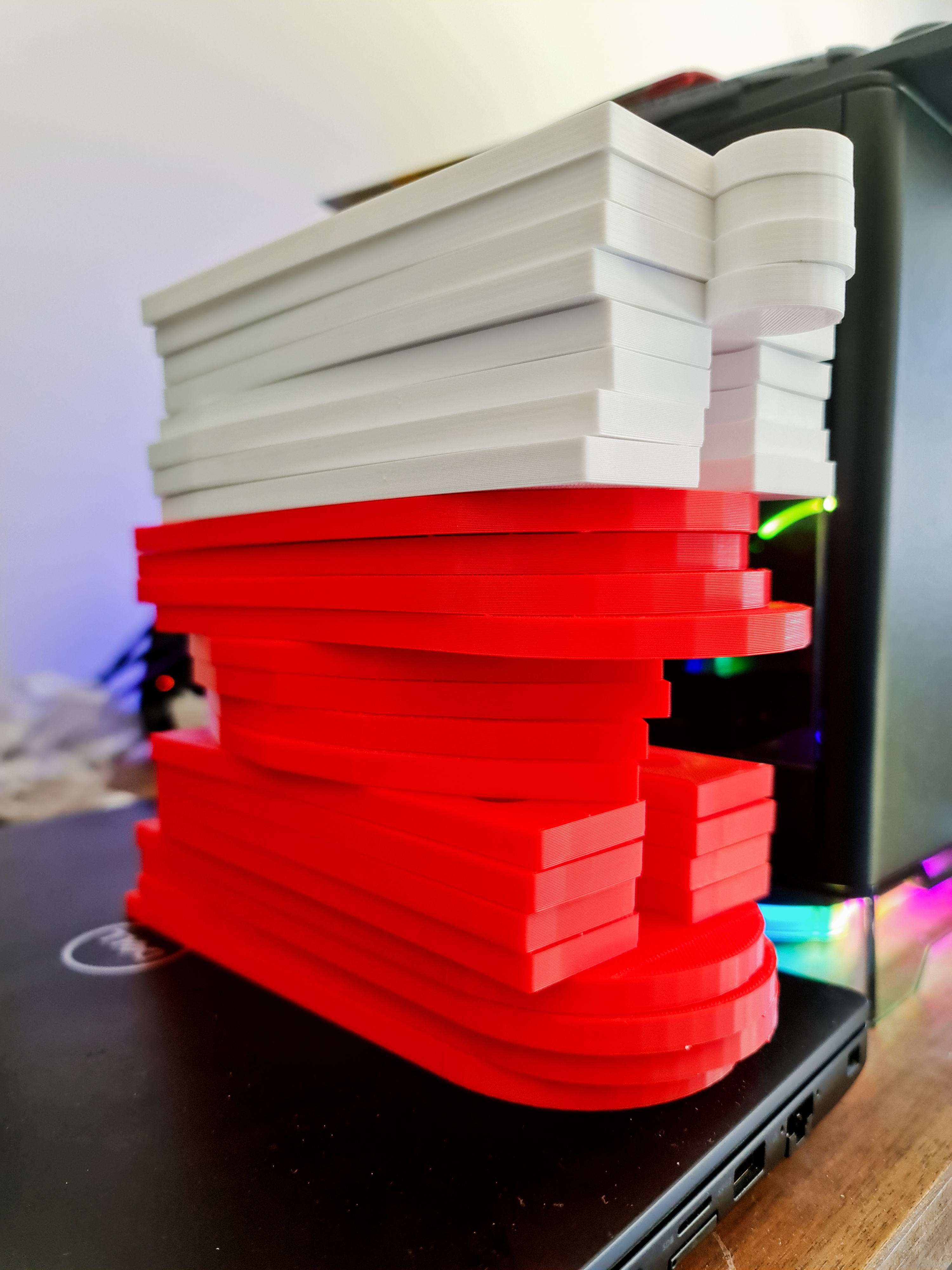
So I designed a 39 bulb Candy Cane. It'd have been nice I think to add another strip in the middle of them but ... these props will probably be replaced next year anyway. So out comes good ol' Sketchup and I start working on a design.
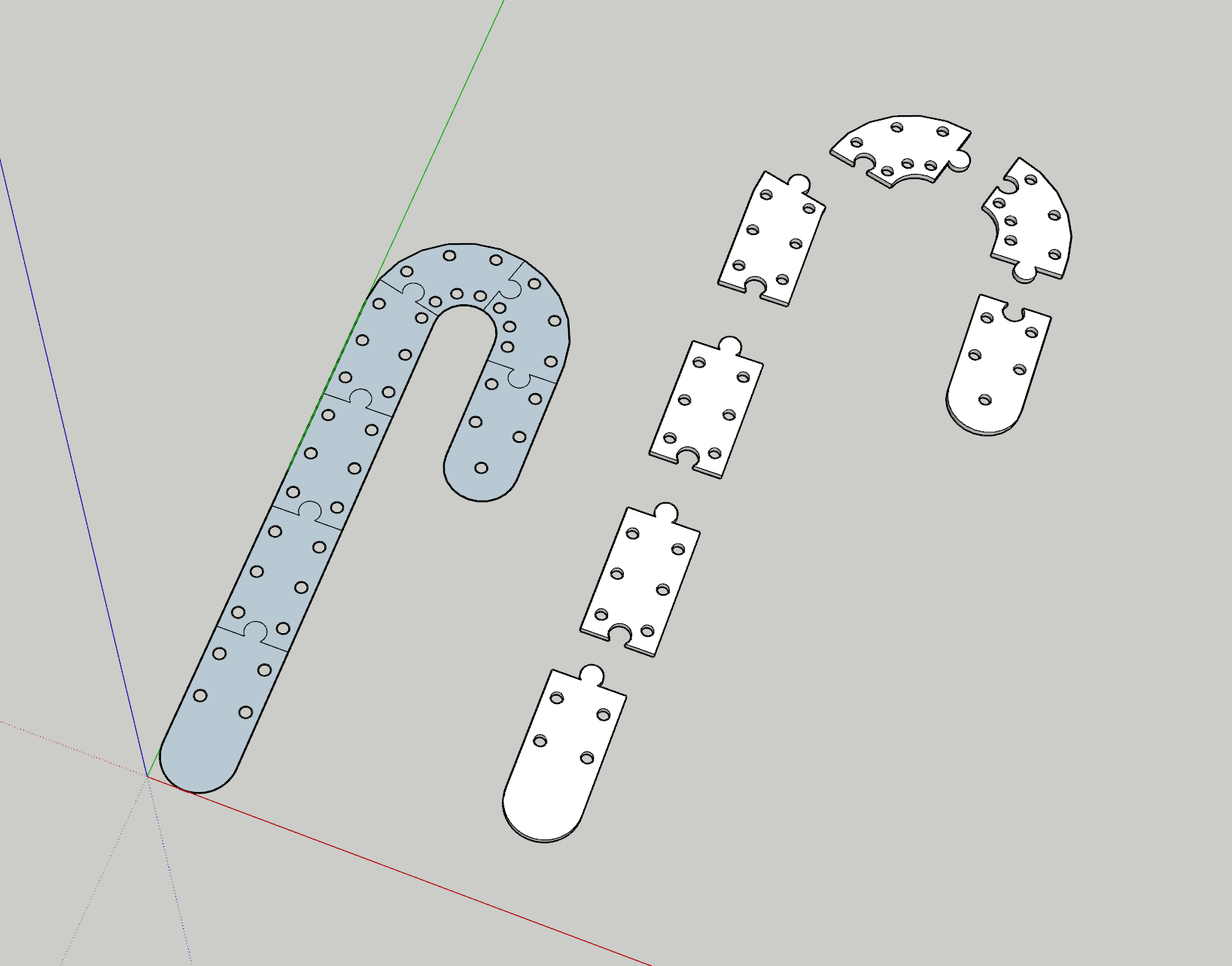
A pretty simple design that in future I'd probably have put some holes in to allow for cable ties to go in the middle rather than around the whole prop. But for this year it should be fine. To make them look a little decorative, I'd alternate white with red ABS. I certainly have plenty of filament so might as well make use of these colours.
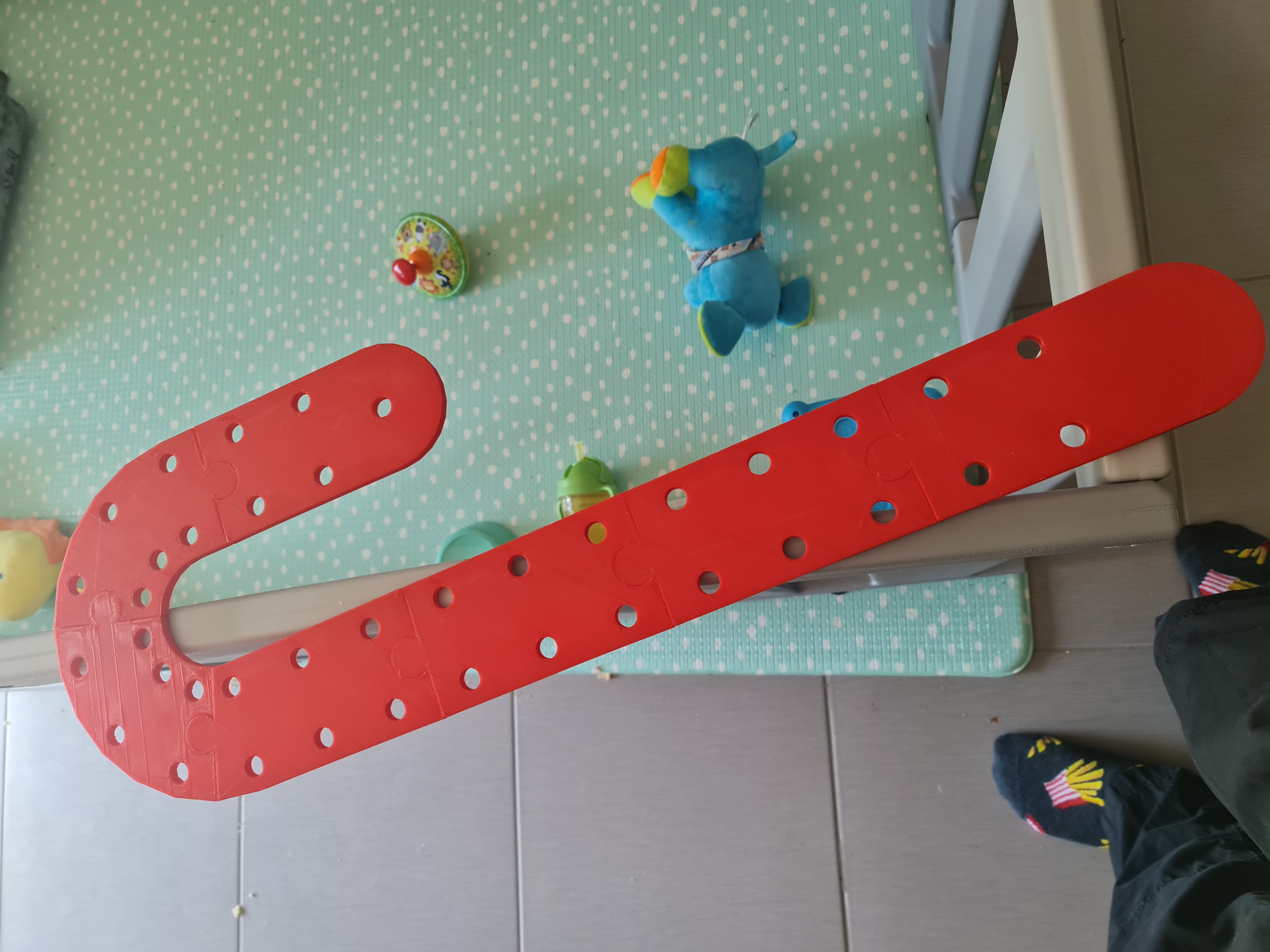
After a day of printing the parts out, I have a good idea on how this is going to look. After wiring a few bulbs in we have some success.
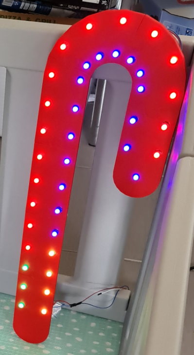
Honestly, having put the pixel tester in and saw it light up - I was a bit underwhelmed. Really needed that middle strip I think but we'll go with the two lines and see what happens. I'm sure I can make some decent effects on it and you'll be seeing it from the footpath anyway. So I digress...
With this one out of the way, it was time to set up a bulk print order...
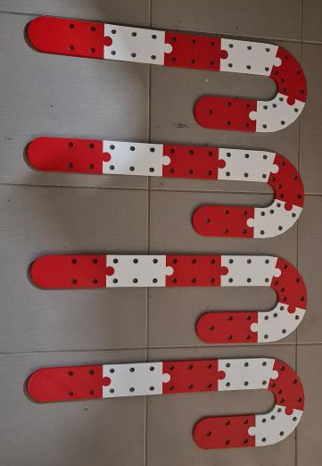
Seeing these fully assembled though - I'm pretty happy with how they look. And most importantly, my son loves them. There's something in the reflectiveness of the white that is intriguing to him.
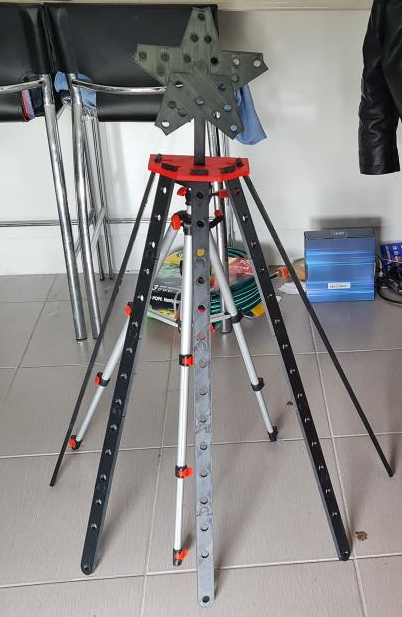
The Mini Tree (with Star)
So the star of the show (ha ha) would be some of the mini trees .They'll carry most of the beats and the more interesting displays but they'd also be the most difficult to print. This is perhaps where a local supplier of Coro material to do it would have been a little more effective but I figured I could print a base with the star to mount to, and have holes for 'spokes' to sit in. I'd use tent pegs to hold the legs in place which gives me a bit of an opportunity to perfect the placement of these bulbs at least for the first year. It's fair to say these'll probably be replaced as well in future.
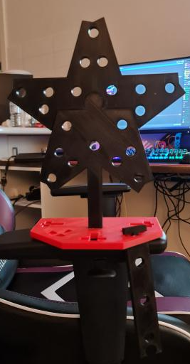
The base is fairly solid. I'd discovered that a 25% Gyroid Infill was a good balance between a rigid structure and weighty enough. But I probably should have printed some sort of base for a PVC Pipe to hold it up. But that's OK... nothing a bit of Loctite won't fix... after all if it's good enough for my brake calliper bolts, it's good enough for my PVC pipe. The plastic cement stuff anyway.
These definitely produce an interesting effect and the adjustable spokes will be good for putting a little bit of personality into the display. Something a bit missing when you carbon copy everything several times.
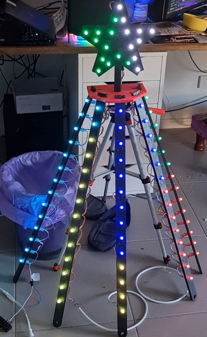
These will definitely look great out on the lawn come Christmas time! Obviously there's some waterproofing to do and more pigtails to solder *sigh* ... but we're good to go on these ones. So queue the bulk print job for another weeks worth of stuff.
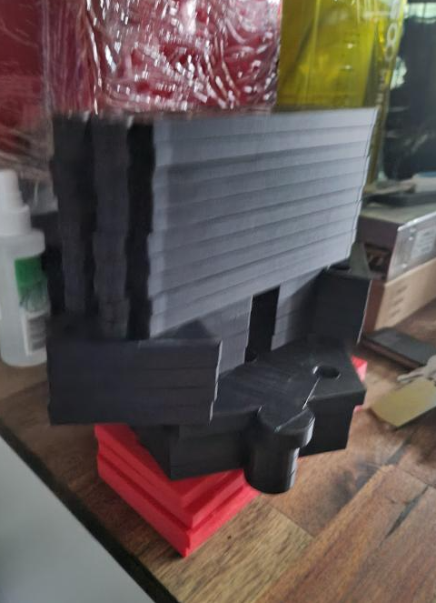
Now I've got to say, all this 3D printing is burning through Filament fast but how much you say? Each of the larger props (Christmas Trees and Santa) were less than a 1KG roll each. With each ABS roll costing around $25 AUD, it's not the most economical product but it is allowing me to print things to the dimensions I want. For a lot of the Candy Cane stuff, Christmas Trees etc... there's probably around a role for the lot - but they are thinner prints and less plastic. But it does take a lot of time to do. The Christmas Tree bases alone - 4 of these in addition to the test tree, was say around 1/4 a role and took over a day. Each spoke needs to be printed 5 times, for 4 trees. They take over a day each and probably consumed 1/2 a role. The stars were similar - a day to do those and took around 1/8 a role. So expect around a week of printing, at least on my printer that runs around 30mm per second. I'm sure that more modern printers are able to run much faster these days and with the right infill models in place you can probably reduce a lot of rework.
Where to from here?
Well, more progress has been made. I've built a sample matrix and even found a use for some cheaper Chinese bulbs that I thought I'd trial. These have been done in the last two weeks, but this post is already 18 images deep so I'll leave it for a couple of weeks and showcase those. I've also got myself heavy into the sequencing game so there's probably at least 3 more posts before the actual show.
I must admit - this has been one of the most enjoyable creativity projects I've worked on in years. Being able to build something with your own hands and see it go is great. Watching your son full of enjoyment when the lights come on takes that to a whole new level. Anyway I hope you've enjoyed seeing the pictures and if you're inspired to start working on things, once again I can recommend taking a bit of a look on AusChristmasLighting for some further inspiration. But be warned - it's not something that you're going to be doing if you've only got a budget for $500 or less.
But ... I am keen on working out what kind of show you could build for $500(ish) if that's something people are interested in next year. There are some good shortcuts and devices you can buy for some light sequencing paired up with some traditional AC-style lights that I recon could be a winner. Also - it looks like Bunnings are getting in on the action with a peculiar Christmas Tree that has individually addressable lights. You can be sure that people are hacking these already to work with the WS2811 protocol. Costco even has these 'Twinkly' branded trees at the time of writing for $199. In any case, it's not a cheap hobby and if you can do some of the tinkering yourself and you already have Ardunio's, Raspberry Pi's and are set up with enough to be dangerous, you can do most of it yourself and save on those dollars.
Anyway - until next time. Ciao!